Jiabaida BMS
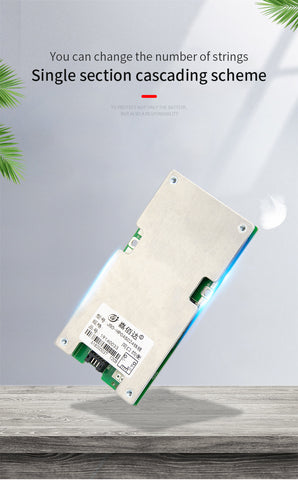
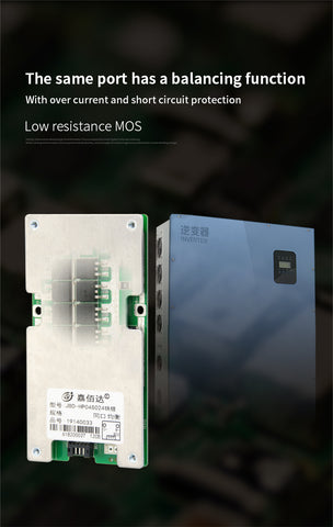
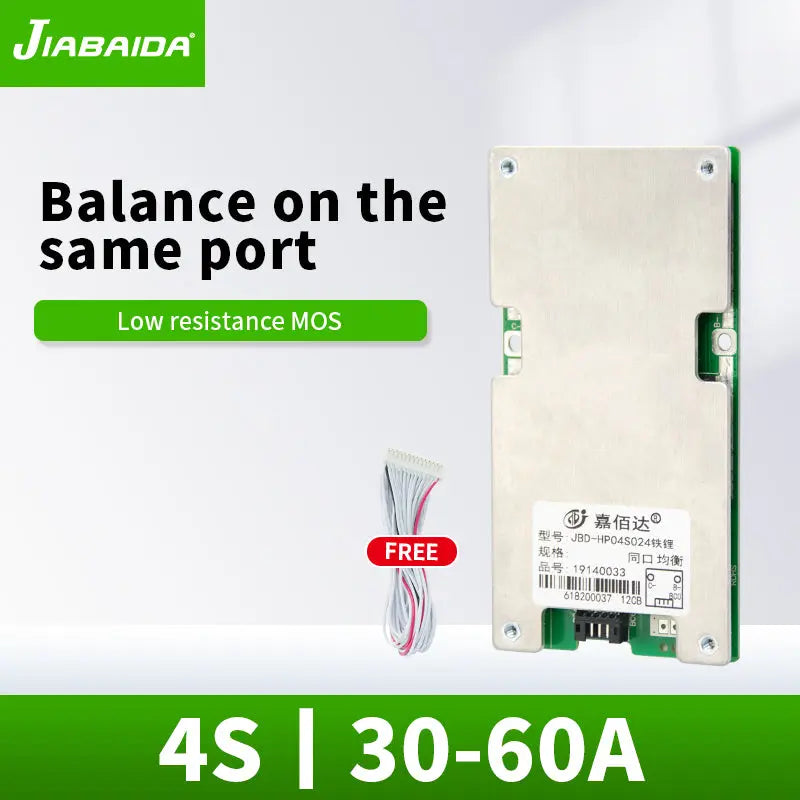
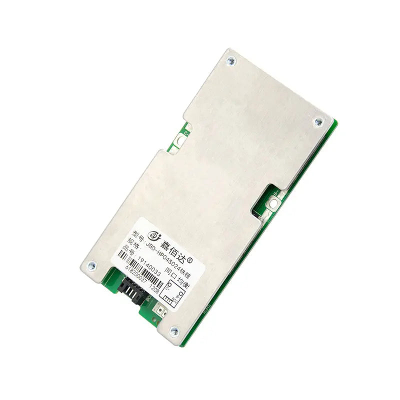
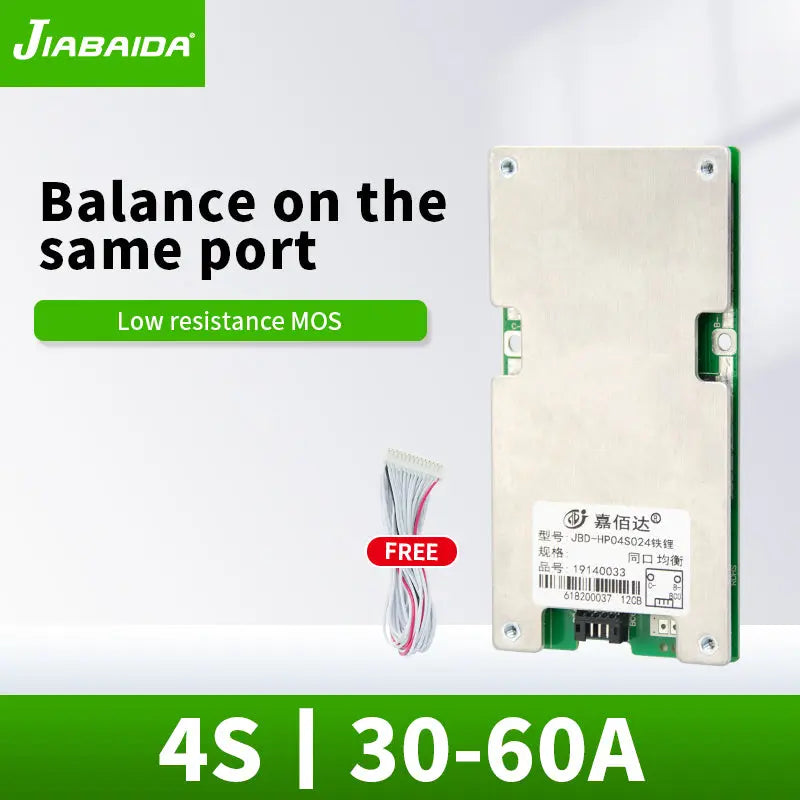
JBD Normal BMS 4S 12V 30A 40A 50A 60A Lifepo4 Lithium Battery PCB with Balance on The Same Port
Couldn't load pickup availability
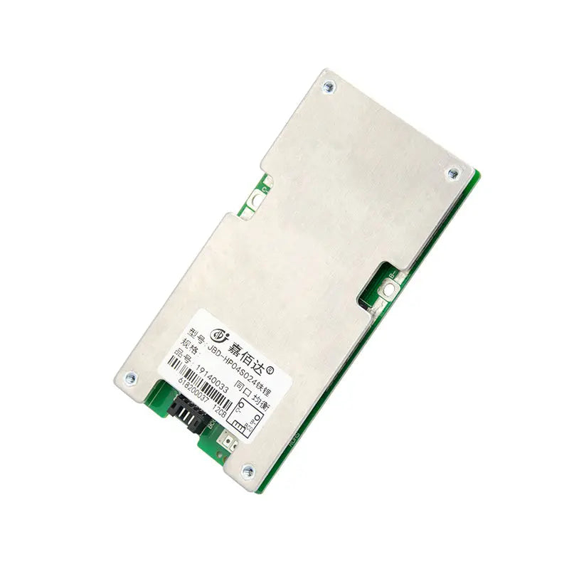
HP04S024 Normal bms
- Model Number: HP04S024
- Type: bms pcba
- Place of Origin: Guangdong, China
- Brand Name: JBD
- Product name: 4s bms lifepo4
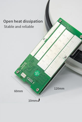
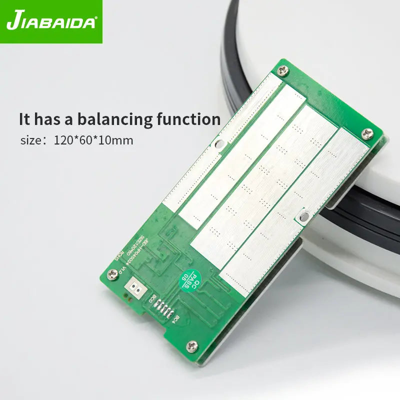
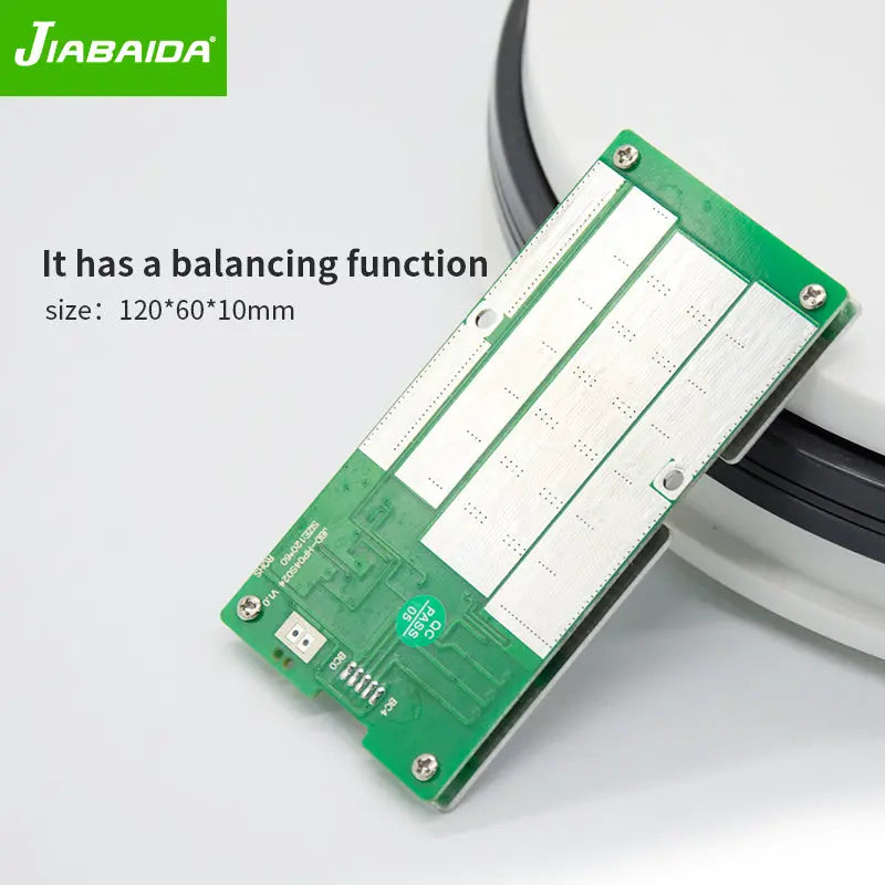
- Size: 120*60*10mm
- Application: Electronic Products
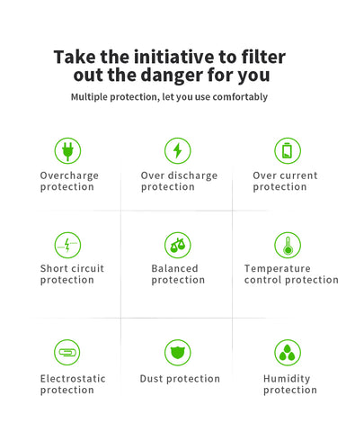
- Short-circuit protection: yes
- Over current protection: yes
- Current: 30a 40a 60a
- Testing Service: 100% Testing
- Voltage: 12v
- Service: EMS.ODM.OEM
- Direct Factory: yes
Packaging & Delivery
- Selling Units: Single item
- Single package size: 23X13X16 cm
- Single gross weight: 1.000 kg
- Package Type: Manufactuers will upgrade the packaging sometimes,please refer to the actual object received.
- Package Content : 1* BMS *Balance wires
-
JBD-HP04S024
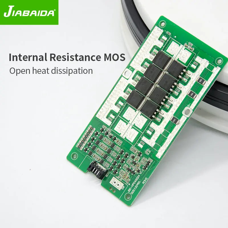
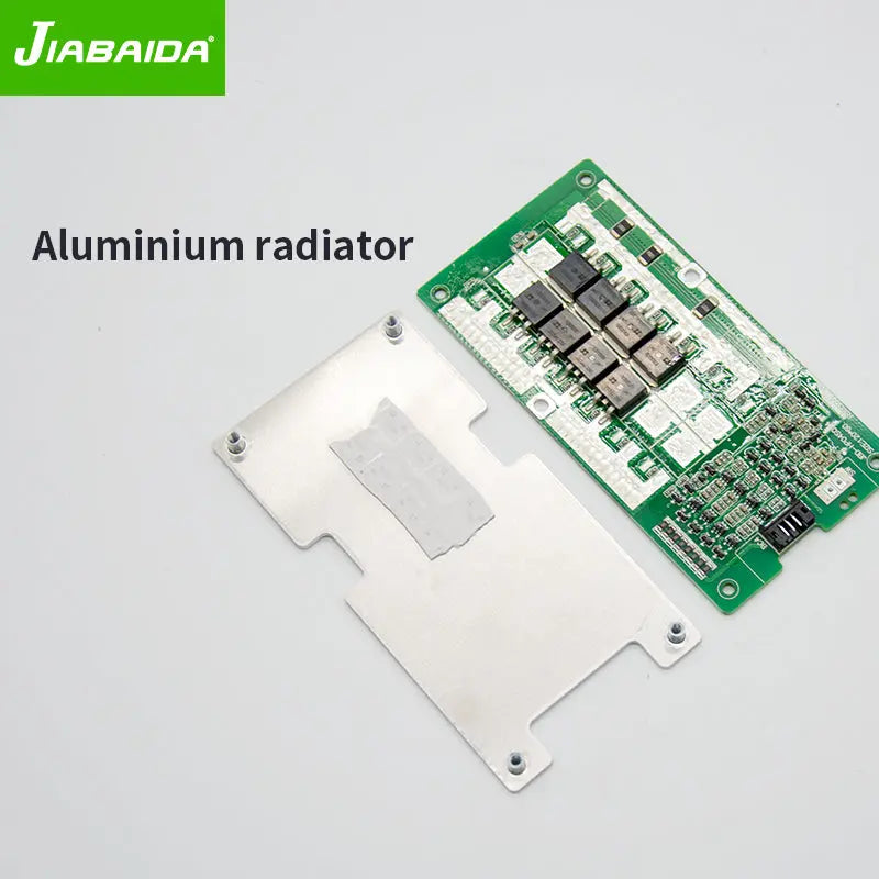
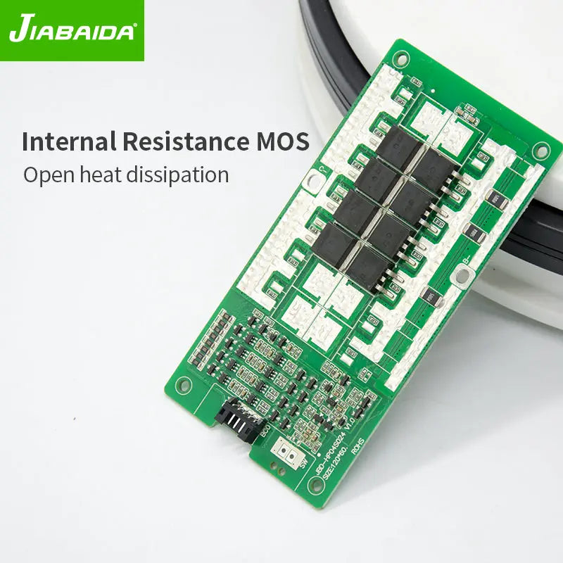
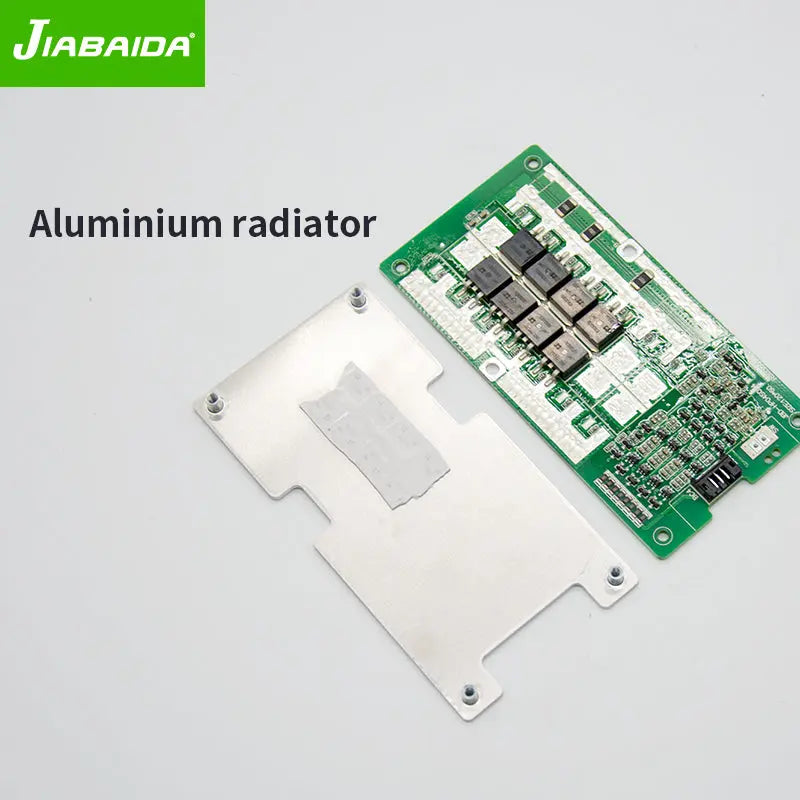
JBD-HP04S024 is designed by Dongguan jiabaida Electronic Technology Co., Ltd. It is an intelligent protection board scheme specially designed for 4 series battery packs of power tools and energy storage products. It is suitable for lithium batteries with different chemical properties, such as lithium ion, lithium polymer, lithium iron phosphate, etc.The protection board has strong load carrying capacity and the maximum continuous discharge current can reach 60A.(1) 4 cell series protection(2) Various protection functions for charging and discharging(3) Hardware discharge over - current, short - circuit protection function processing(4) Reserved temperature protection function(5) Very low static consumption current(6) Balance functionOperating voltage range:8.4-15V Operating current (MAX): 60A Over-charge protection voltage: 3.75±0.05V Over-discharge protection voltage:2.1±0.1V Balanced turn-on voltage:3.6±0.05V Internal resistance:<10mΩ
-
Protection function description
Overcharge protection: When the battery is under the charging state, the voltage keeps going up. When the protection board detects that the voltage of any cell is higher than the overcharge protection value, the protection board will start timing immediately. When the time reaches the overcharge protection delay, the protection board will turn off the charging MOS tube, at that time, it cannot be charged.
Overcharge protection recovery: After the overvoltage protection appears on the protection board, the battery voltage will going down under the static or discharge state of the battery. When the protection board detects that each voltage is lower than the recovery voltage of the overcharge protection, the protection board will output a signal and turn on the charging MOS tube to charge.Over-discharge protection: When the battery is under the discharge state, the voltage keeps going down. When the protection board detects that the voltage of any cell is lower than the overcharge protection value, the protection board will start timing immediately. When the time reaches the over discharge protection delay, the output signal of the protection board will turn off the discharge MOS tube, the load lock circuit will work, but, it cannot discharge at this time.
Over discharge protection recovery: After the over discharge protection appears on the protection board, the battery voltage will going up under the static or discharge state of the battery. When the protection board detects that each voltage is higher than the recovery voltage of the over discharge protection. At this time, disconnect the load or charge, the protection board will output a signal and turn on the charging MOS tube to charge.
Overcurrent protection: When the battery is under the static or discharge state, the current suddenly increases. When the protection board detects that the current reaches the overcurrent protection value, the protection board will start timing at that time. When the current duration in the circuit reaches the overcurrent protection delay time, the output signal of the protection board will turn off the discharge MOS tube, and the load lock circuit will work. At this time, the discharge cannot be conducted.
Overcurrent protection recovery: After the discharge overcurrent protection appears on the protection board, the discharge MOS tube is turned off, and the current in the loop becomes 0. At this time, the load is disconnected or charged, the output signal of the protection board will turn on the discharge MOS tube to discharge.