Jiabaida BMS
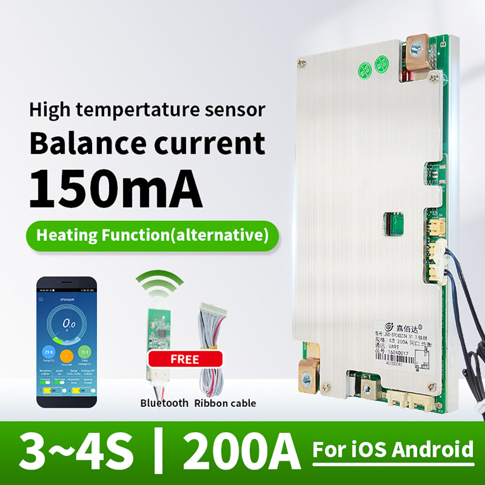
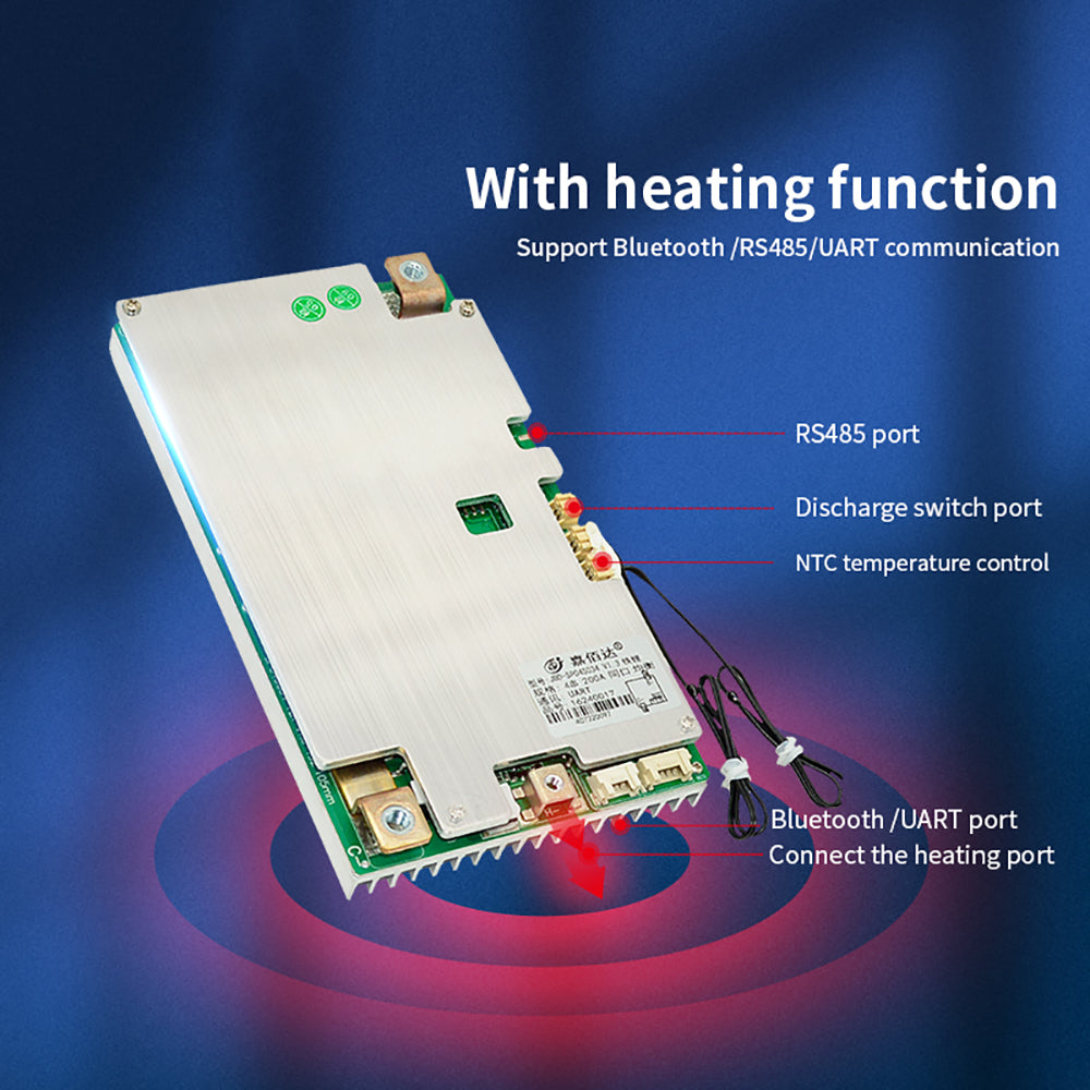
JBD Smart bms 3S 4S 100A 120A 150A 200A LiFePO4 Battery PCB with Uart Heating Function & Series Connection
Couldn't load pickup availability
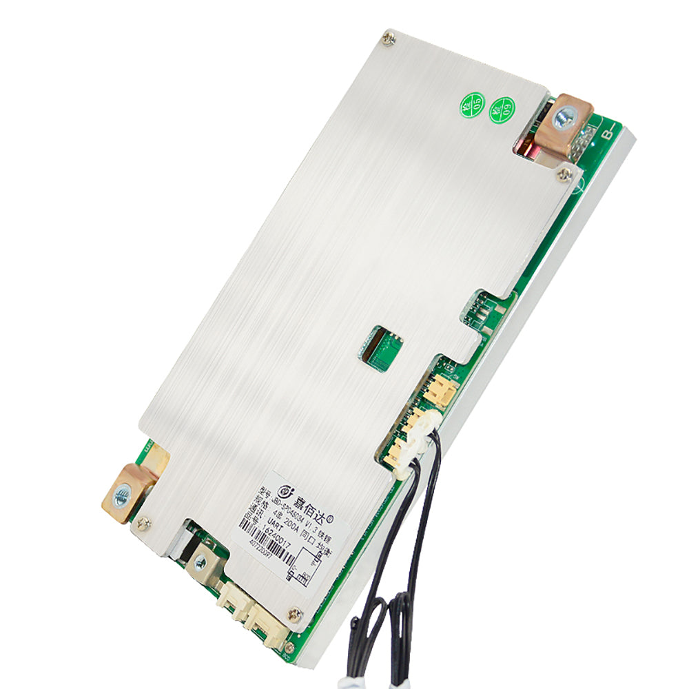
SP04S034 Smart bms
BMS Lifepo4 Details :
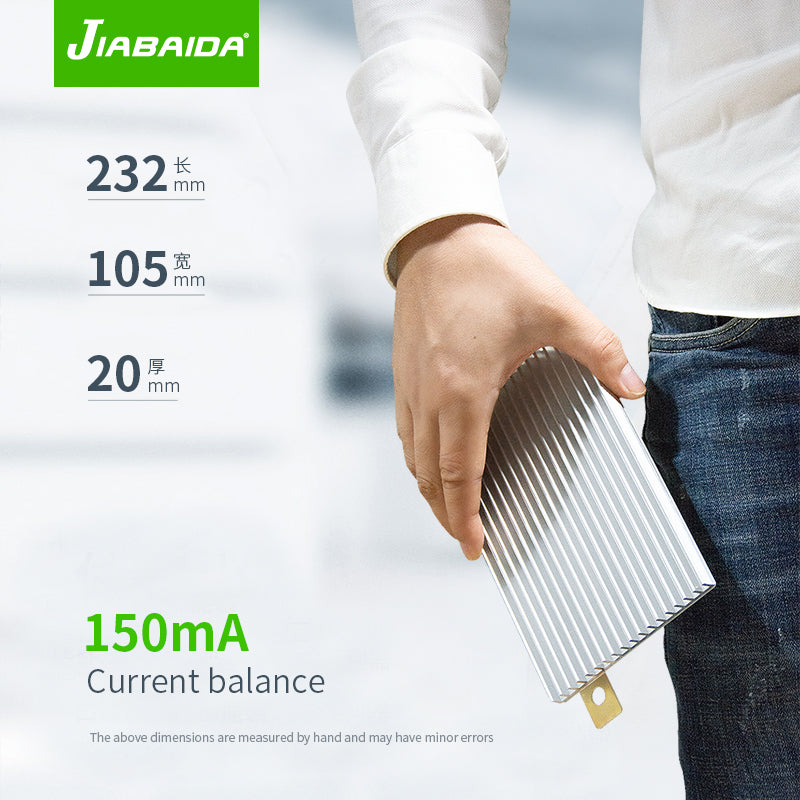
| Operating Current (MAX) | 150A |
| Connection Port | same port for charge and discharge |
| Charge voltage(recommend) | 14.4V |
| Working voltage range | 9.2v-15.0v |
| Short Circuit Protection | Yes |
| Internal Resistance | <10mR |
| Working Temperature | -30 degree~75 degree |
| Discharge Protection overtemperature | 72~78 degree |
| Charge Protection overcurrent | 160~200A |
| Discharge protection undertemperature | -25-15 degree |


Protection function description
Overcharge protection: When the battery is under the charging state, the voltage keeps going up. When the protection board detects that the voltage of any cell is higher than the overcharge protection value, the protection board will start timing immediately. When the time reaches the overcharge protection delay, the protection board will turn off the charging MOS tube, at that time, it cannot be charged.
Overcharge protection recovery: After the overvoltage protection appears on the protection board, the battery voltage will going down under the static or discharge state of the battery. When the protection board detects that each voltage is lower than the recovery voltage of the overcharge protection, the protection board will output a signal and turn on the charging MOS tube to charge.
Over-discharge protection: When the battery is under the discharge state, the voltage keeps going down. When the protection board detects that the voltage of any cell is lower than the overcharge protection value, the protection board will start timing immediately. When the time reaches the over discharge protection delay, the output signal of the protection board will turn off the discharge MOS tube, the load lock circuit will work, but, it cannot discharge at this time.
Over discharge protection recovery: After the over discharge protection appears on the protection board, the battery voltage will going up under the static or discharge state of the battery. When the protection board detects that each voltage is higher than the recovery voltage of the over discharge protection. At this time, disconnect the load or charge, the protection board will output a signal and turn on the charging MOS tube to charge.
Overcurrent protection: When the battery is under the static or discharge state, the current suddenly increases. When the protection board detects that the current reaches the overcurrent protection value, the protection board will start timing at that time. When the current duration in the circuit reaches the overcurrent protection delay time, the output signal of the protection board will turn off the discharge MOS tube, and the load lock circuit will work. At this time, the discharge cannot be conducted.
Overcurrent protection recovery: After the discharge overcurrent protection appears on the protection board, the discharge MOS tube is turned off, and the current in the loop becomes 0. At this time, the load is disconnected or charged, the output signal of the protection board will turn on the discharge MOS tube to discharge.
